

Why Injection Location Is as Important as Chemistry Selection
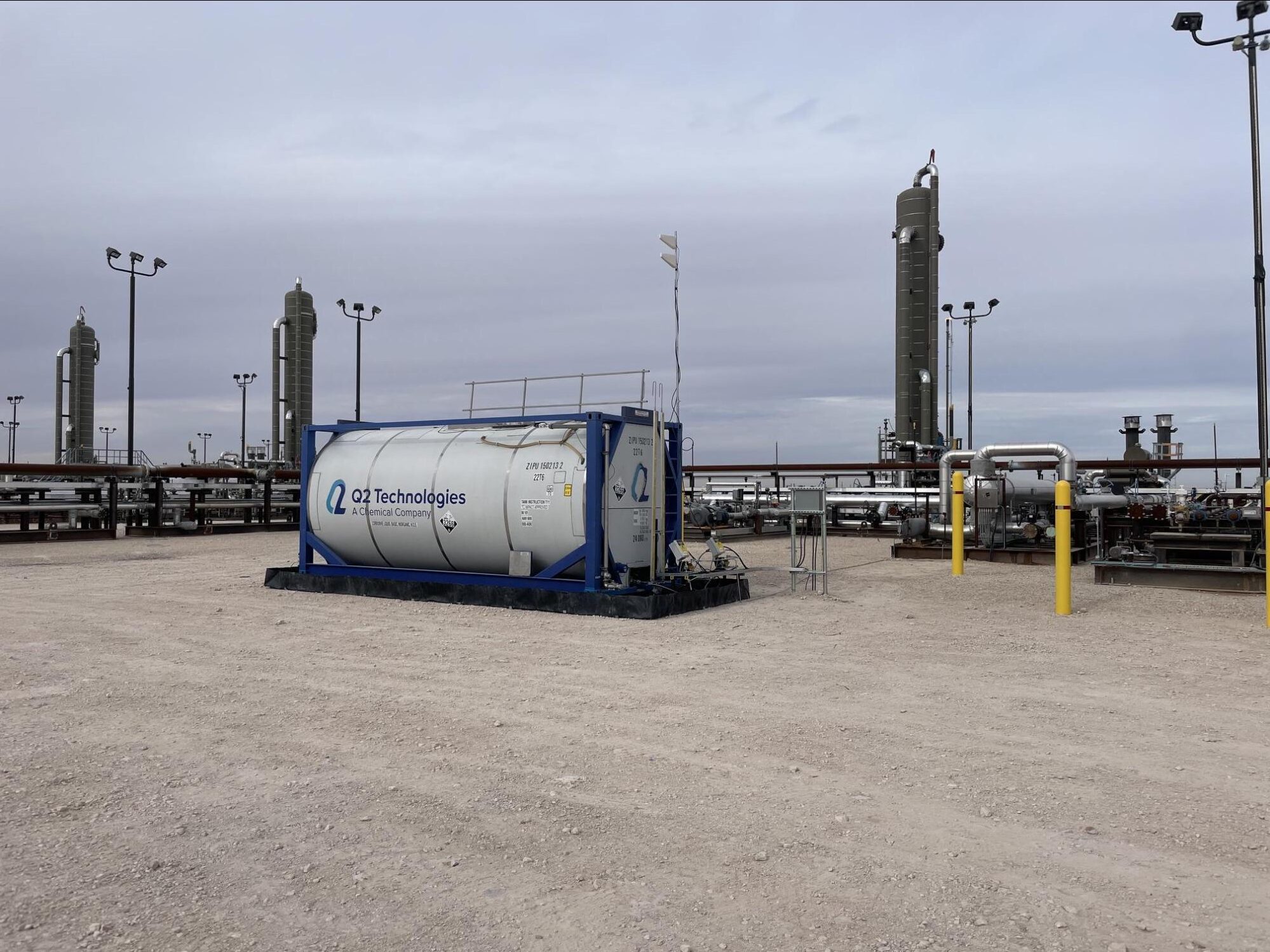
Tank battery operators often focus heavily on which scavenger chemistry to use, but injection point selection has just as much influence on treatment performance. The same triazine or non-triazine scavenger can perform very differently depending on where it enters the system, how much mixing and contact time it gets before the treated fluid reaches the tank, and whether it is treating liquid, vapor, or both.
At a typical tank battery, H2S can be present in the incoming produced fluid, in flash gas released as pressure drops across separators and into stock tanks, and in vapor space above the liquid level. Each of these locations may need a different treatment strategy.
Treating the Liquid Stream
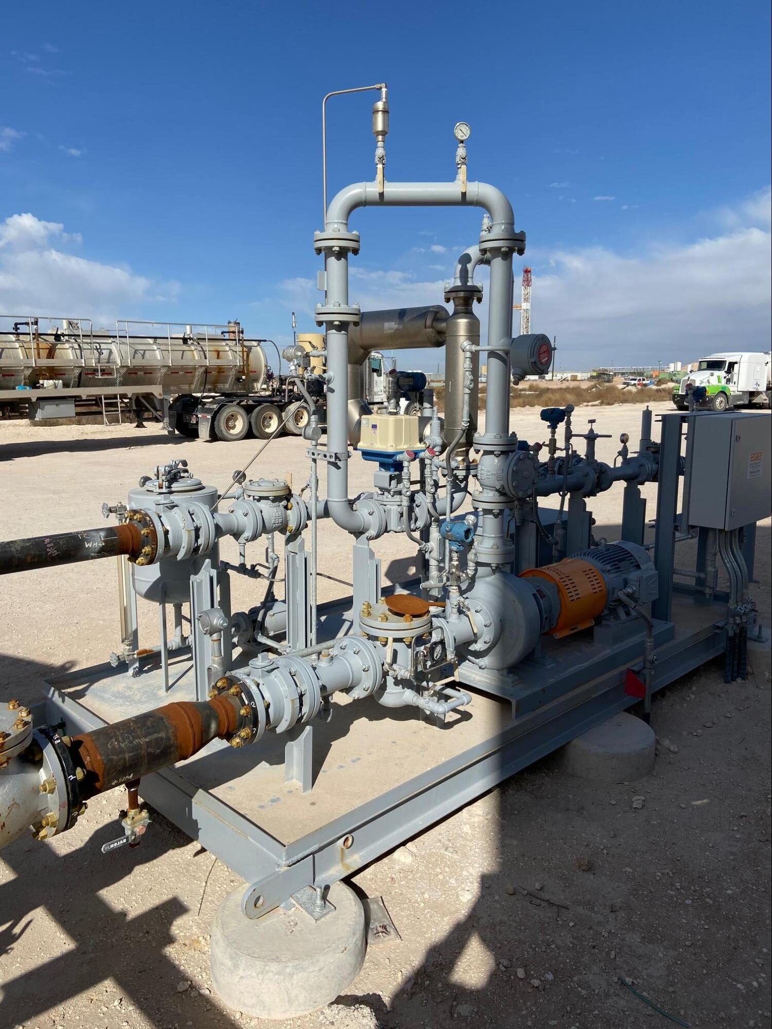
Liquid-phase injection, typically ahead of a separator or upstream of the tank inlet, works best when there is enough pipe length and turbulence downstream of the injection point to achieve good mixing. Scavenger injected directly into a low-velocity line or too close to the tank inlet may not have adequate contact time to react fully with dissolved H2S before the fluid reaches the vessel, reducing effective treatment even though the correct chemical volume was injected.
A static mixer or a section of pipe with elbows and fittings downstream of the injection quill can meaningfully improve scavenger performance compared with injection into a straight run of pipe with minimal turbulence.
Treating Flash Gas and Vapor Space
H2S that flashes out of solution as pressure drops into the tank presents a separate treatment challenge, since scavenger dosed only into the liquid stream will not necessarily address vapor-phase H2S released after that point. Vapor-phase treatment options include tank-top scavenger units, vapor scrubbing towers, or scavenger pads and cartridges sized to the expected vapor volume and H2S concentration.
Operators sometimes find that a liquid-phase program alone controls H2S in the stock tank fluid but fails to address odor or worker exposure concerns around the tank hatch, which is a sign that flash gas and vapor space need their own dedicated treatment point rather than relying on upstream liquid treatment to carry through.
Accounting for Multiple Tanks and Battery Layout
Batteries with multiple tanks in series or parallel need injection strategy that reflects how fluid actually moves through the system. A single injection point ahead of the entire battery may undertreat downstream tanks if there is significant flashing or degassing between vessels. In these layouts, secondary injection points or vapor-phase treatment at individual tanks are often more reliable than relying on one upstream dose to carry through the whole system.
Practical Guidance for Field Selection
Before finalizing an injection point, it helps to map where H2S actually shows up in the system using portable detection equipment at the separator outlet, tank inlet, and tank vapor space, rather than assuming a single wellhead measurement represents the whole battery. Matching injection location to where H2S is actually generated or released, and confirming adequate mixing and residence time at that point, tends to produce more consistent results than selecting a chemistry first and assuming any injection point will work.
Seasonal and Production Changes
Injection point performance is not necessarily fixed once selected. Seasonal temperature swings can change how much gas flashes at a given pressure drop, and declining reservoir pressure over the life of a well can shift where in the system H2S is released relative to where it was released during early production. A quill placement and mixing setup that worked well when a battery was first commissioned can become less effective years later as flow rates and flash behavior change, which is worth revisiting during routine facility reviews rather than only when a treatment complaint arises.
Coordinating With Injection Rate
Injection point and injection rate should be evaluated together rather than in isolation. A well-placed quill with inadequate mixing can still underperform at low dosage, while excessive dosage at a poorly placed quill wastes chemical without solving the underlying contact time problem. Field verification through H2S testing at multiple points downstream of the injection quill, not just at the final tank, gives a clearer picture of whether the combination of location and rate is actually achieving the intended reduction.
Documenting the Setup for Field Personnel
Once an injection point has been selected and validated, documenting the reasoning behind it, including the mixing analysis and any test data used to confirm performance, helps field personnel understand why a quill is located where it is rather than treating placement as arbitrary. This documentation becomes particularly valuable when a battery changes hands between operators or when new personnel are assigned to a location, since it prevents a well-designed injection setup from being altered or relocated without understanding the original basis for its placement.