MEA-triazine – A Hydrogen Sulfide Scavenger for Natural Gas Operations

case-study4

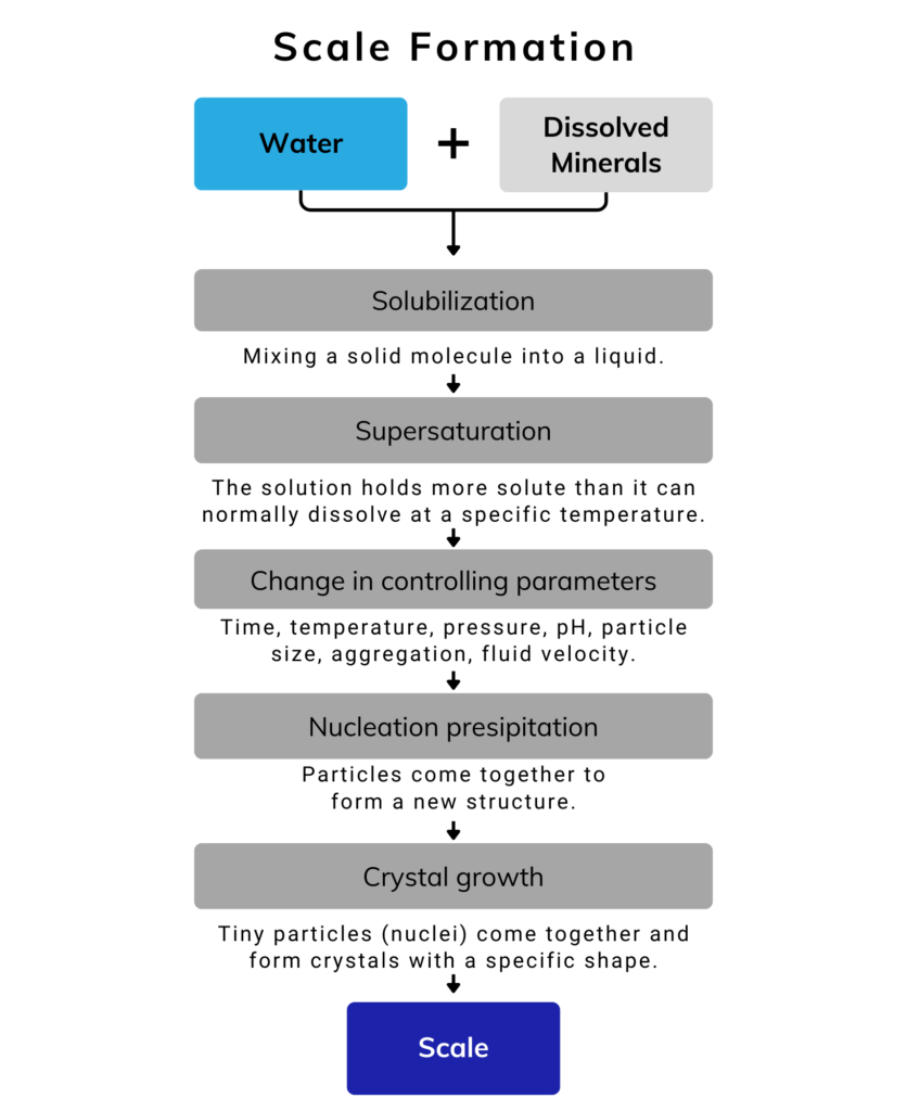
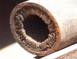
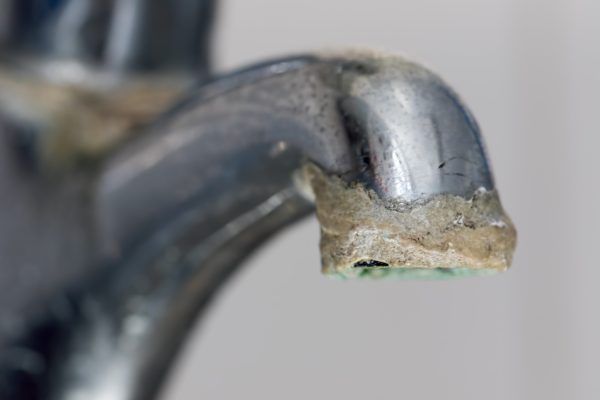
Hydrogen sulfide (H2S) is a hazardous, corrosive, and toxic gas that can be found in oil and gas production. Its rotten egg smell is a distinctive marker and it is flammable. The smell can be detected at very low concentrations (about 1ppm), which serves as a warning as H2S is extremely toxic: at levels of 100ppm, inhalation of it can be fatal. In addition to being extremely toxic, H2S can cause severe corrosion issues to equipment. To avoid these operational risks and to meet commercial specifications, H2S must be removed from natural gas. According to general industry standards, gas is considered sour if it contains more than 4ppm of H2S.

What is MEA-Triazine?

There are many chemicals being used in the gas sweetening process, an MEA Triazine based H2S scavenger is one of the most common.


MEA Triazine (also known as Monoethanolamine Triazine, or simply just triazine) is a clear to light yellow liquid with a mild amine odor, which has a fishy smell. Triazine cannot be used in its pure form and so various concentrations of the product are manufactured, common field strength levels range from 20 to 80%. Its primary application is to remove hydrogen sulfide from gas and oil. Custom formulations based on this product can be blended with various polymers and additives to enhance or decrease certain attributes found in the natural gas stream.

Application Methods of MEA Triazine

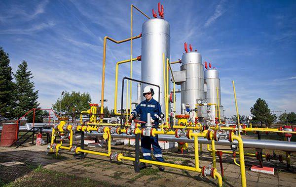
Direct Injection, Contactor Tower

In many applications, triazine is injected directly into the gas stream. When there is good injection flow and enough time to respond, this approach works for H2S removal. Due to the H2S dissolving into the product, typical efficiencies are lower, although a removal efficiency of around 40% is to be expected. The location of the injection and the product choice must be carefully considered for direct injection to be successful. Atomizers, fog nozzles and static mixers tend to be used when applying MEA Triazine via direct injection.
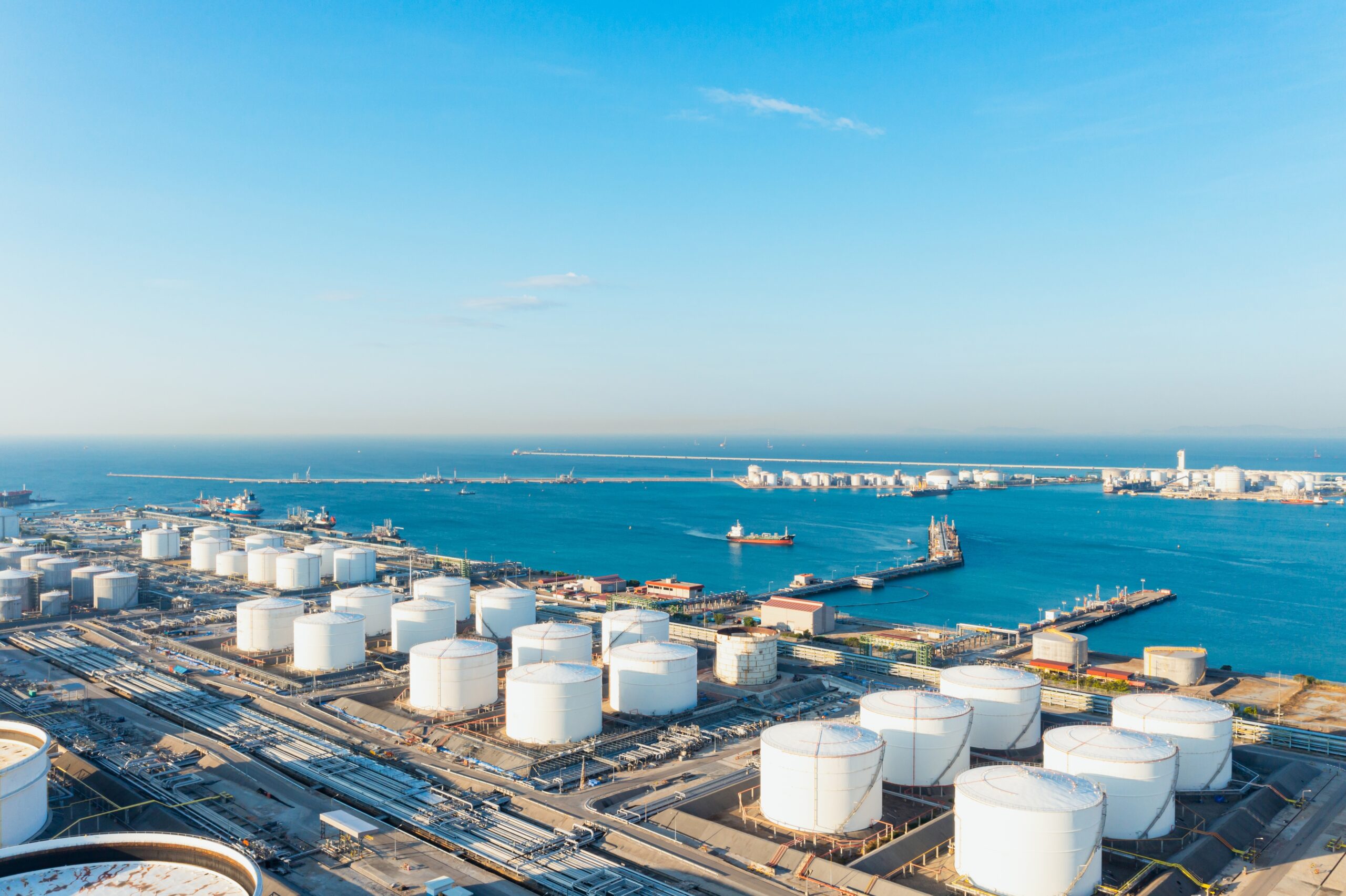
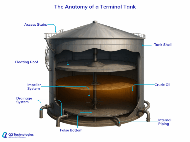
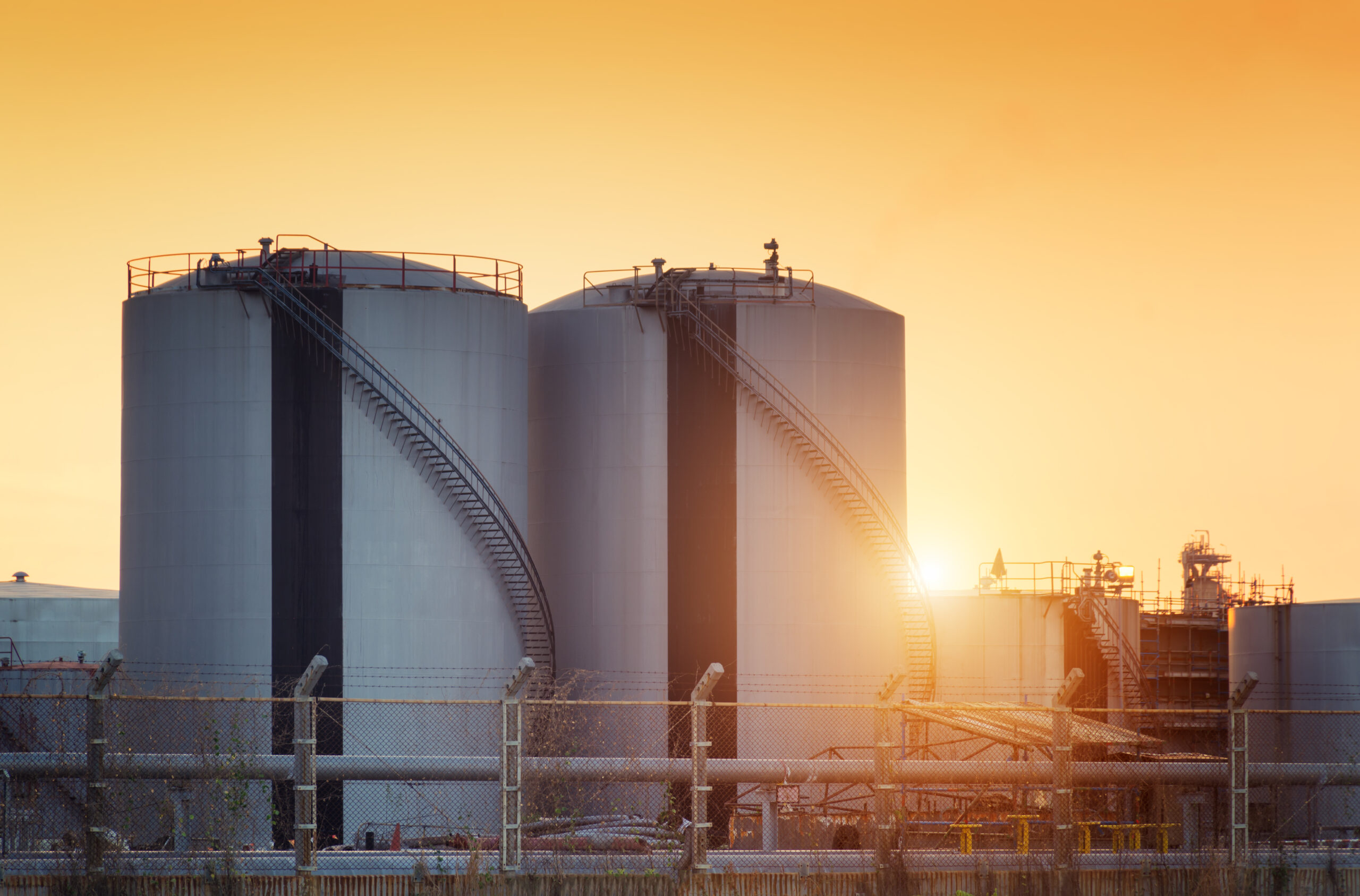

Contactor Tower

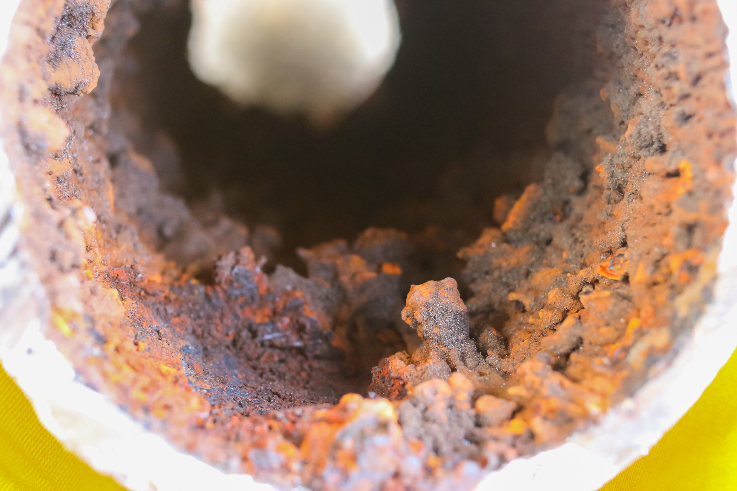
Another common approach is routing sour natural gas through a triazine-filled contactor tower. The tower layout can take on a variety of designs, but essentially H2S is eliminated when the gas passes through the liquid and dissolves into the triazine. The H2S removal efficiency of contactor towers can reach up to 80%. As a result, much less chemical is used, and OPEX may be significantly decreased. The contactor tower and chemical storage tanks, however, are less useful for offshore use since they take up a lot of room and weight.

Benefits of Q2 Technologies’ MEA Triazine

  • Simple treatment with a low investment.
  • When buying directly from the manufacturer you may reduce H2S scavenger costs.
  • Up to 80% active triazine with other dilutions available.
  • Over 20 years’ experience as Triazine manufacturers along plus applied engineering support.
  • Turn-key automated skids for lease or purchase.
  • Specialty blends with a variety of inhibitors.

Natural Gas Treatment Case Study

A major gas producer in Southeast Texas was using a mixture of 10 drums of fresh water with Sodium Nitrate for the removal of H2S in their contact tower. The run time equated to two months before change-outs were necessary. After each run, the tower trays were removed and the system steam cleaned in order to remove the precipitated sulfur and other deposits that had accumulated on the interior wall of the sparger. This process included a labor crew and steam-cleaning unit. The clean-out time ran from one to two days depending on the severity of disposition.

Case Study 305: Southeast Texas Results

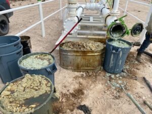
Due to ongoing sulfur deposition and labor intensive change-outs, Q2 Technologies was invited to test our triazine process utilizing the same tower. Calculations indicated that a 50% reduction in total product would achieve the same results as the Sodium Nitrite. Five drums of triazine and five drums of fresh water were added to the contractor.

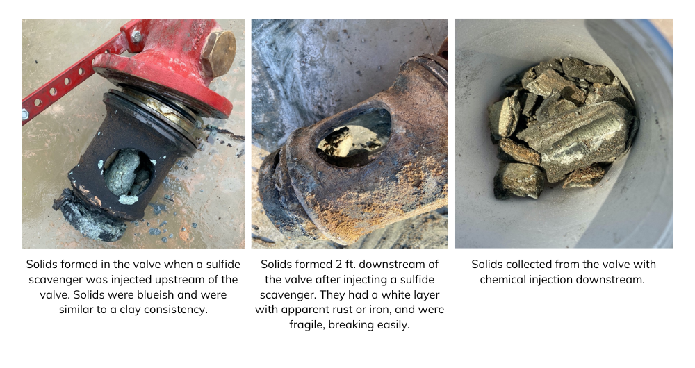
It was determined after the two-month test period, that our triazine achieved the same performance as Sulfa-Check with half as much product. In addition, the vessel was found to be free of solids upon inspection. There was no clean out involved and the reacted product was easily drained and the tower recharged.


Download this case study here.

Other Chemistries for H2S Removal

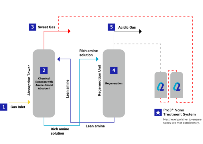
MEA-Triazine is an effective solution for H2S removal. However, each application is different and may require different scavenger alternatives. At Q2 Technologies, we also offer a non-triazine/non-amine H2S scavenger solution: Pro3® Nano. This alternative is a low CAPEX modular solution designed to lower LOE compared to conventional triazine scavengers. Learn more about the differences between Triazine and Non-Triazine for H2S Treatment and find the best solution for your operations. The Pro3® Nano chemical process is specifically designed to treat sour gas volumes using a unique combination of nano particles in a contact tower with a regenerative cycle.

What’s the best solution?

The best solution is whatever works best for your application. The main goal will always be H2S removal, but there are financial, operational, and commercial considerations that must be weighted.

  • Have all KPIs (Key Performance Indicators) been identified and quantified?
  • In doing so, are OPEX and CAPEX being optimized?
  • Are the assets suffering from corrosion or over/under utilization?
  • Is the hydrocarbon stream meeting commercial ppm requirements or thresholds?

These are some ideas to consider when choosing suitable treatment solutions, it not only depends on reaching H2S level requirements, but also on seeing how the scavenger affects your project as a whole. At Q2 Technologies we can help provide recommendations based on your specific needs, contact us and we’ll help you find exactly what you need to treat your sour gas.


Sources:


https://prism.ucalgary.ca/bitstream/handle/1880/112374/ucalgary_2020_du_steven.pdf?sequence=2&isAllowed=y

http://static1.squarespace.com/static/53556018e4b0fe1121e112e6/54b683d0e4b09b2abd348a7b/54b683e4e4b09b2abd348e9a/1421247460293/GATEKEEPER-H2S-Scavenging-Triazine.pdf?format=original

The Anatomy of a Terminal Tank: Inside a Crude Oil Storage Giant

Terminal tanks are critical assets in the midstream oil and gas sector. These massive structures store millions of barrels of crude oil and other hydrocarbons at key logistics hubs across the globe. But what exactly is going on inside these tanks?

In this blog, we take a look under the hood — or rather, under the roof — of a crude oil terminal tank to better understand its internal components, operational purpose, and why each element matters for safety, efficiency, and product integrity.

What Is a Terminal Tank?

A terminal tank, often located at storage terminals near refineries, ports, or centralized locations in the field—commonly known as terminals or terminal hubs—is designed to hold large volumes of crude oil or refined products. These tanks serve as buffers in the oil supply chain, enabling reliable transportation, blending, or further processing. In terms of crude oil movement, once a barrel enters a tank, its movement can temporarily stop to allow for volume accumulation. This is particularly important for FERC-regulated pipelines, which require barrels to “come to rest” before crossing certain state or federal boundaries.

Did You Know? 
Terminal tanks are deeply tied to the development of the U.S. pipeline system and federal regulation. When longer pipelines were first being developed, crude oil sources were often far from refineries, which tended to be near population centers. As pipelines began crossing state lines to bridge that gap, the federal government had to step in to establish a common regulatory framework. This ensured that states could operate under mutual standards and that smaller or less-established shippers could access markets without being pushed out by larger players. This need led to the formation of the Federal Energy Regulatory Commission (FERC). Today, FERC continues to oversee aspects of crude oil transportation and tank terminal design as part of the interstate system. 

The most common type used in crude storage is the atmospheric floating roof tank, which minimizes vapor losses and helps reduce emissions. 

Cross-Section of a Terminal Tank: Key Components

Here’s a breakdown of the critical internal components typically found in a crude oil terminal tank:

1. Floating Roof

  • Function: Sits directly on top of the oil surface, rising and falling with product level.
  • Purpose: Minimizes the vapor space above the liquid, reducing volatile organic compound (VOC) emissions.
  • Types: External floating roof (EFR) and internal floating roof (IFR), the latter being enclosed by a fixed roof to reduce weather impact.
2. Tank Shell
  • Structure: A cylindrical steel wall that contains the product.
  • Design: Built to API 650 standards, often over 100 feet in diameter and 40+ feet tall.

3.  Impeller or Mixing System

  • Role: Maintains homogeneity in the stored product, especially important for stabilized crude blends.
  • Types: Jet mixers, spargers, or mechanical agitators, depending on tank size and content type.

4. False Bottom (Optional)

  • Purpose: Allows for heating coils or drainage channels beneath the actual storage floor.
  • Benefit: Prevents water accumulation and sludge settling, improving product recovery and reducing corrosion risk.

5. Drainage System

  • Includes: Internal drains and sump systems.
  • Function: Facilitates removal of water bottoms and sediment; critical for tank maintenance and cleaning operations. 

6. Internal Piping

  • Inlet/Outlet Lines: Control product entry and exit.
  • Recirculation Lines: Allow product mixing or transfer to other tanks.
    • This can be as simple as a transfer pump moving crude from one tank to another. More advanced systems can portion certain volumes to a fully manifold system.
  • Vapor Recovery Lines: Connect to vapor control systems to meet environmental regulations.

7. Access Ports and Manways

  • Usage: Entry points for inspection, sampling, or maintenance.
  • Safety:Equipped with gas detection and fall protection features for confined space entry compliance.
8. Behind the Scenes
  • Control Room:Every modern tank terminal has a dedicated team of professionals responsible for coordinating with on-site personnel. These control room operators may be located on-site or, more commonly, at a remote location. They are typically staffed 24 hours a day and work in shifts to ensure continuous operation without downtime. Operators may have override authority based on multiple redundant readings—such as pressure, temperature, and volume—to help prevent human error in the field. Additional measures are often taken to keep these control rooms secure, including hardening their network connections.

Why This Matters: Operational and Safety Implications

Understanding the anatomy of a terminal tank isn’t just technical curiosity — it’s critical for: 

  • Product integrity: Uniform storage reduces stratification and contamination. 
  • Regulatory compliance: Emission controls and safe venting systems are essential for meeting environmental standards. 
  • Maintenance planning: Access to internal systems allows for proactive corrosion monitoring and efficient cleaning. 
  • Safety and incident prevention: Proper design minimizes risks of tank overfills, vapor ignition, and structural failure.

The Role of H2S Scavenging in Tank Operations

Many crude oils — especially sour crudes — contain hydrogen sulfide (H2S), a toxic and corrosive gas. Inside terminal tanks, H2S can accumulate in the vapor space or be released during tank breathing.


That’s why integrating H2S scavenging solutions is crucial for:

  • Worker safety during sampling or maintenance
  • Equipment longevity by reducing corrosion risks
  • Compliance with OSHA and EPA regulations

At Q2 Technologies, our non-triazine H2S scavengers are widely used across terminals to ensure safe, effective crude storage and handling.

Final Thoughts: Every Tank Tells a Story

Terminal tanks may look simple from the outside, but inside, they are complex systems engineered for performance, safety, and reliability. Whether you’re planning storage capacity, managing emissions, or optimizing product handling, understanding tank anatomy is foundational to smarter operations.

Want to learn more about tank treatment technologies or H₂S mitigation at your terminal? 
Contact Q2 Technologies to speak with our experts.

Back to Basics: H2S Removal in Natural Gas Operations

Hydrogen sulfide (H2S) is a major concern in upstream crude oil and natural gas production, midstream transport, and downstream refining. It’s a colorless gas with a distinct rotten egg odor, but its dangers go far beyond its smell. At high concentrations, H2S is highly toxic, corrosive, and explosive, requiring operators to implement efficient removal strategies to protect personnel, equipment, and product quality.

While the fundamental methods of H2S removal have been established for decades, the industry is continuously evolving. Operators today must balance performance, cost efficiency, environmental impact, and regulatory compliance. In this blog, we’ll break down the latest insights into H2S removal in Natural Gas, covering traditional and emerging technologies, their advantages and limitations, and what the future holds for H2S management.

As Natural Gas production grows, effective H2S management becomes increasingly important. Let’s take a closer look at how emerging technologies are addressing these challenges in the Natural Gas sector.

Why H2S Removal is Critical in Natural Gas

The presence of H2S in hydrocarbon production can be present in crude oil, natural gas, and produced water, but today we’re focusing on H2S in Natural Gas, which, when present creates multiple challenges:

1. Health & Safety Risks

H2S is extremely toxic. According to OSHA and other health related regulatory agencies which tend to focus on permissible levels for safe work conditions, less than 20 ppm is generally accepted to be safe. At concentrations above 100 ppm, it can cause severe respiratory issues, and at 700 ppm or higher, it can be fatal in just a few breaths. Ensuring proper removal before transport or processing reduces worker exposure risks and improves site safety.

Image Source: https://en.gazdetect.com/gas-information/h2s-hydrogen-sulfide-gas-detector/ https://www.osha.gov/laws-regs/regulations/standardnumber/1910/1910.1000TABLEZ2

2. Corrosion & Infrastructure Damage

H2S reacts with metals, leading to sulfide stress cracking (SSC) and pipeline corrosion. Uncontrolled H2S levels can reduce the lifespan of equipment and increase maintenance costs. Proper removal mitigates these risks and ensures long-term asset integrity.

3. Regulatory Compliance

Environmental and safety regulations impose strict limits on H2S emissions and pipeline transport specifications. For example:

  • The EPA regulates H2S emissions , along with 118 other contaminants, under the Clean Air Act due to its role in acid rain and air pollution.
  • Pipeline gas transmission standards (such as those set by the GPA Midstream Association) limit H2S to as low as 4 ppm to prevent infrastructure damage and ensure downstream compatibility.

4. Gas Marketability

H2S reacts with metals, leading to sulfide stress cracking (SSC) and pipeline corrosion. Uncontrolled H2S levels can reduce the lifespan of equipment and increase maintenance costs. Proper removal mitigates these risks and ensures long-term asset integrity.

Overview of H2S Removal Technologies

There is no one-size-fits-all approach to H2S removal. The best method depends on factors like gas composition, flow rate, temperature, and operational constraints. Below, we break down the most widely used removal technologies:

1. Amine Gas Sweetening (Regenerative Absorption)

How It Works:

Best For:

Limitations:

2. Non-Regenerative H2S Scavengers (Chemical Scavenging)

How It Works:

  • Scavengers chemically react with H2S, forming stable, non-volatile byproducts.
  • The most common scavenger type is triazine-based, but newer formulations are emerging to reduce operational issues like scaling.

Best For:

Limitations:

Advancements in Scavengers:
New scavenger technologies are improving efficiency, reducing environmental impact, and addressing common industry challenges. Traditional triazine-based scavengers, while effective, can lead to issues such as scaling, high chemical consumption, and increased wastewater treatment costs.

At Q2 Technologies, we’ve developed innovative H2S scavengers that outperform conventional options by providing:

  • Non-Triazine Solutions – Pro3® GT Series: Our Pro3® GT non-triazine scavengers eliminate common byproduct issues like scale buildup in pipelines and production equipment. This results in cleaner operations, reduced downtime, and lower maintenance costs.

  • Enhanced Efficiency & Cost Savings: Our scavengers are designed for optimal performance, requiring lower chemical dosages to remove H2S effectively. This translates to reduced operating costs and improved treatment consistency.

3. Oxidation & Catalytic Processes

Emerging oxidation and catalytic technologies are gaining traction due to their environmental benefits.

Examples Include: 

  • Liquid Oxidation Systems: Convert H2S into elemental sulfur or sulfate compounds using liquid catalysts.
  • Direct Catalytic Oxidation: Uses metal catalysts to convert H2S to sulfur or sulfur dioxide without generating large waste streams.
  • Dry Scavenger Technology – Pro3® Nano: Unlike traditional liquid scavengers that require significant handling and disposal efforts,Pro3® Nanodry, solid-based H2S scavengerthat simplifies logistics, improves safety, and minimizes waste. This makes it an excellent choice for operators looking for a safer and more efficient alternative.

Best For:

4. Claus Process (Sulfur Recovery)

How It Works: 

  • Used in large-scale gas processing, the Claus process converts H2S into elemental sulfur through controlled combustion and catalytic reaction stages. 
  • The recovered sulfur is often sold for industrial use (fertilizers, chemicals, etc.). 

Best For:

Limitations:

What’s Next for H2S Removal?

As the oil and gas industry evolves, so do H2S removal strategies. Several key trends are shaping the future:

Smarter H2S Monitoring & Control

  • Real-time gas analysisallows operators to detect and adjust H2S treatment instantly.
  • AI-driven automation is optimizing scavenger dosing to minimize chemical waste and reduce costs.

Lower-Impact Chemical Scavengers

  • Non-triazine scavengers are eliminating concerns about pipeline scaling and wastewater treatment.
  • Eco-friendly formulations are gaining popularity to meet stricter environmental regulations.


Sustainability & Sulfur Utilization

  • Some operators are exploring new ways to repurpose recovered sulfur for commercial or industrial use.
  • Lower-emission technologies are helping reduce the carbon footprint of H2S removal processes.

Choosing the Right H2S Removal Solution

Selecting the best H2S removal technology depends on:

  • H2S concentration & gas flow rate – Higher concentrations often require regenerative systems, while lower levels may be best suited for scavengers.
  • Operational constraints – Remote or offshore locations may favor non-regenerative solutions due to space limitations.
  • Economic factors – Long-term operating costs, chemical consumption, and potential sulfur recovery benefits should be considered.
  • Regulatory requirements – Compliance with safety and emissions regulations is essential when choosing a removal method.

At Q2 Technologies, we specialize in innovative, cost-effective H2S removal solutions tailored to today’s operational challenges. Whether you need reliable scavengers, advanced monitoring, or expert consultation, we help you optimize performance and compliance.

Need help with H2S removal? Contact us today to learn more about our customized solutions.

Final Thoughts

H2S removal is more than just a regulatory requirement—it’s a critical factor in worker safety, asset integrity, and product quality. As the industry shifts toward smarter, cleaner, and more efficient treatment solutions, staying informed on the latest advancements is key to maintaining a competitive edge.

By understanding the fundamentals and leveraging new technologies, operators can maximize efficiency, reduce costs, and ensure long-term compliance in an ever-changing regulatory landscape.

Understanding Lease Automatic Custody Transfer (LACT) Units in Midstream Operations

In oil and gas midstream operations, Lease Automatic Custody Transfer (LACT) units play a crucial role in ensuring the accurate measurement and transfer of crude oil from production sites to pipelines or storage facilities. LACT units automate the process of measuring, sampling, and transferring crude oil while meeting regulatory and contractual specifications.

How a LACT Unit Works

A LACT unit is a self-contained system designed to measure and transfer crude oil efficiently while ensuring that only merchantable-quality oil enters the midstream network. The process follows several key steps:

  1. Oil Enters the LACT System: Crude oil is pumped into the LACT unit from a booster pump.
  2. Sampling: a sample pot collects a representative sample of the crude for quality analysis. Sampling depends on the frequency of maintenance.
  3. Filtration & Water Separation: Initial filtration removes debris and free water separation helps prevent excessive water from entering the pipeline. Not all LACTs may be equipped with dedicated filtration or separation, rather, if the water detection system registers high BS&W, it would automatically divert the entire volume back to the heater treater for further separation.
  4. Measurement: The Coriolis meter provides highly accurate mass and volumetric flow measurement.
  5. Quality Verification: The unit checks for unacceptable levels of water, sediment, or contaminants that could impact the oil’s marketability.
  6. Transfer to Pipeline: If the oil meets specifications, the control valve automatically opens and allows oil to flow to the pipeline, if not, it may be bypassed or rejected.

Learn more about buildup and flow issues in crude systems in our Scale 101: Part 1 article.

The Role of the Coriolis Meter

A key component of the LACT unit, the Coriolis meter provides precise real-time measurements of mass flow, density, and temperature. Unlike traditional turbine meters, Coriolis meters offer greater accuracy and reliability by directly measuring the mass of the crude oil rather than relying on volumetric displacement. This is critical in detecting water contamination and ensuring proper custody transfer accounting.

The Sample Pot and Its Importance

The sample pot, or composite sampler, collects a continuous and proportional sample of crude oil during transfer. This sample represents the entire batch being moved and is analyzed for water content (BS&W – basic sediment and water), sulfur, iron, and other contaminants. The results of these tests determine if the crude oil meets pipeline specifications.

How a LACT Unit Works

A LACT unit is a self-contained system designed to measure and transfer crude oil efficiently while ensuring that only merchantable-quality oil enters the midstream network. The process follows several key steps:

  • Excessive Water Content: If the crude contains high levels of BS&W (above pipeline specifications, often 0.5% or less), it must be treated or rejected.
  • H2S Presence: Hydrogen sulfide (H2S) is a hazardous gas that makes crude oil dangerous to handle and transport. If detected beyond acceptable limits, the oil may require additional treatment or be rejected outright (learn more about our H2S removal products).
  • Iron & Sediment Contamination: These can cause pipeline corrosion, fouling, and equipment damage, making the oil non-merchantable.
  • Meter Calibration Issues: The Coriolis meter must be regularly calibrated to ensure measurement accuracy.
  • Valve & Pump Failures: Mechanical failures in the system can lead to improper transfers, inaccuracies, or downtime.

Crude Oil Quality and Marketability

For crude oil to be considered merchantable and accepted into midstream infrastructure, it must meet specific quality parameters. Common contaminants that lead to rejection or bypassing include:

  • Water (BS&W exceeding limits): Excessive water reduces crude value and requires further processing.
  • Hydrogen Sulfide (H2S): High levels pose safety hazards and can lead to pipeline corrosion.
  • Iron & Sediment: Particulate matter can damage refining equipment and pipelines.
  • API Gravity Variations: Crude must meet API gravity specifications to ensure consistency in processing.

Conclusion

LACT units are vital in ensuring accurate, efficient, and safe custody transfer of crude oil in midstream operations. With key components such as the Coriolis meter for precise measurement and the sample pot for quality verification, these systems help enforce crude oil specifications. However, challenges such as excessive water, sediment, H2S, or other contaminants can lead to rejection, emphasizing the importance of monitoring and maintaining oil quality before transfer. Proper operation, maintenance, and monitoring of LACT units ensure compliance with pipeline requirements and help maximize the value of crude oil in the marketplace.

Need help with H2S removal or midstream measurement challenges? Contact Q2 Technologies to speak with our experts.

Hydrogen Sulfide in the Pulp and Paper Industry

Hydrogen Sulfide in the Pulp and Paper Industry

Hydrogen Sulfide (H2S) is a toxic substance that can be found in several industries, including oil and gas, landfill and biogas, wastewater treatment, and pulp and paper. In today’s blog, we’ll focus on the pulp and paper industry, exploring how H2S is a common byproduct of the process and discussing ways to mitigate this noxious gas.

The History and Importance of Papermaking.

Papermaking has been around for quite a while – in fact, it dates back to the first century AD. Further, papermaking has commonly been associated as one of the Great Four Inventions of China, alongside the compass, gunpowder, and printing. Prior to the 1800s, papermaking was very much an artesian process of mold-shaped papers. Since then, however, with more and more automation and consistent quality standards, pulp and paper products have become essential components of various industries. Regardless of individual usage, it is nearly impossible to avoid consuming commercial or domestic paper goods in the modern world.

We’ll dive into the complexities and concerns surrounding H2S in the pulp and paper process in a minute. But first, let’s recognize that today, despite the digital focus we have on modern applications and services, the pulp and paper industry remains one of the largest industries in the world. Unsurprisingly, nations that have a plethora of timber and other pulp sources are leading the way, namely the United States, China, Brazil, and Canada as some of the major players contributing to this globalized product.

Global Leaders in the Pulp and Paper Industry

United States

  • Pulp Imports: China is the world’s largest importer of wood pulp, with imports surging to over 1.9 million metric tons in 2024. This is driven by its massive paper production capacity and increasing demand for paper-based products.
  • Paper Production: China leads globally in paper production, exceeding 100 million metric tons annually, and continues to invest in expanding its production capacity to meet domestic and international demand (UNECE).

  • Consumption: China has one of the highest per capita consumption rates of paper products globally, primarily due to the rapid expansion of e-commerce and packaging needs (ResourceWise).

China

  • Pulp Production: The U.S. is one of the largest producers of pulp, generating over 46.7 million metric tons of pulp annually, making it a global leader in pulp production.

  • Paper Production and Consumption: The U.S. produced over 70 million metric tons of paper and paperboard in 2022. The consumption of paper products remains high, driven by packaging materials, though there’s been a shift toward sustainable and recycled materials.

  • Imports: Despite its large production capacity, the U.S. imports pulp and paper products, particularly from countries like Brazil, to meet its internal demand (ResourceWise) (UNECE).

Brazil

  • Pulp Production: Brazil is the third-largest pulp producer, with its focus on market pulp, particularly kraft pulp. It has rapidly expanded production and is expected to increase capacity by 2024. The country is also the top producer of kraft pulp globally.

  • Exports: Brazil is a major exporter of pulp, especially to countries like China and the U.S. Its pulp exports are driven by abundant forest resources and sustainable forestry practices (ResourceWise)

Canada

  • Pulp and Paper Production: Canada is a significant player in both pulp and paper markets. It produces around 8 million metric tons of pulp annually. Canada is known for its softwood pulp, which is highly valued for making high-strength paper products.

  • Exports: Canada exports a significant portion of its pulp, particularly to the U.S., and also exports paper products. The country’s paper production is diversified, including newsprint, packaging, and printing paper (UNECE).

  • Sustainability: Canada’s industry is heavily focused on sustainable forestry and the use of recycled materials, contributing to its competitive position in global markets (UNECE).

Pulp and Paper Industry Leader Snapshot

Managing Hydrogen Sulfide (H2S) in Pulp and Paper Processes

Managing H2S Risks

The concerns around H2S in the pulp and paper making process are attributed to several factors, namely the mechanical and chemical process employed to breakdown pulp and the noxious byproducts these processes generate. This is of serious concern for individuals who work around this type of equipment and must stay vigilant to ensure their safety. In the Kraft process, wood chips are cooked in a solution of sodium hydroxide (NaOH) and sodium sulfide (Na2S). During this cooking process, organic sulfur compounds are converted into H2S and other sulfur gases. The release of H2S can occur at several stages of the process, including:

  • Digesters: Wood chips are cooked in a vessel with a mixture of chemicals known as white liquor, under high temperature and pressure. This breaks down the lignin and separates the cellulose fibers.

  • Pulp Washing: The resulting pulp is washed to remove dissolved lignin and chemicals, off gassing continues to occur.

  • Evaporators: The spent cooking liquid, white liquor, is collected and a concentrate forms, known as black liquor.

  • Recovery boilers: Black liquor can be burned to recover chemicals and generate en

Handling and mitigating H2S in the pulp and paper industry involves several strategies to ensure safety and compliance with environmental regulations here are a several of the main examples:

  • Gas collection: Treatment infrastructure such as scrubber towers is used to capture H2S, which is piped to incinerators that burn it into sulfur dioxide (SO2).

  • Chemical processes: Oxidation or alkaline substances are used to treat or neutralize H2S.

  • Bioreactors: Biological microorganisms are introduced to convert the H2S into sulfates.

Process optimization is a key consideration throughout this process. Implementing one or several of the above-mentioned practices, among others, including leak detection initiatives, will greatly reduce the amount of H2S generated and lessen the risk of employees being exposed to this deadly gas.

Dealing with H2S effectively does require managing certain costs related to equipment upkeep, chemical spend, and safe operations. However, these costs are balanced by economic drivers: regulatory compliance, which avoids fines and penalties for non-compliance; worker safety, which reduces health risks and associated costs from H2S exposure; and increased productivity, as optimized runtimes help mitigate interruptions due to H2S issues.

To learn more about how Q2 Technologies is transforming the pulp and paper industry’s approach to managing H2S, click here to connect with our team.

Sources:

https://www.statista.com/markets/410/topic/961/pulp-paper/#overview

AI-Driven Trends in H2S Safety: Future Innovations

With the recent attention and advent of AI on more products and services, how AI could trend a positive influence on the dangers of H2S is something worth exploring. Through recent news articles and research, a few topics surfaced: utilizing AI and IoT in the workplace, integrating AI into wearable tech, and even with performance monitoring in sport equipment which was being used in the 2024 Paris Olympics. These topics represent just the tip of the iceberg for the future of wearable technology that could have profound implications for better safety measures when it comes to dealing with H2S. So, this got us thinking about potential future trends in safety… H2S safety! Let’s explore some creative and imaginative ways to implement these possible concepts in the near-term with today’s technology.

What Are the Latest Advances in H2S Detection Technology?

Ensuring workplace safety from hydrogen sulfide (H2S) exposure has traditionally depended on strategically placed sensors. While these sensors are valuable, they have their limitations. Recent advancements in H2S detection technology are set to revolutionize this approach. Real-time monitoring systems, such as wireless sensor networks and smart sensors, now provide continuous data across entire areas, unlike point sensors that offer readings only from specific locations. This comprehensive monitoring enables a quicker response to potential leaks that might otherwise go unnoticed.


Personal gas detectors, often bulky and limited in their data output, are also seeing innovative transformations. New wearable technology is stepping up safety measures significantly. Modern personal gas detectors are now compact and comfortable, offering continuous monitoring and real-time alerts for workers. Health-monitoring wearables further enhance safety by tracking potential exposure symptoms, adding an extra layer of protection.

Moreover, drone-based monitoring equipped with H2S sensors is overcoming the challenge of inaccessible or hazardous sensor placements. Drones efficiently scan large and hard-to-reach areas, providing a comprehensive view of gas distribution that traditional methods cannot match. This technology ensures a thorough and proactive approach to workplace safety in the oil and gas industry.

What’s New in H2S Personal Protective Equipment (PPE)?

While traditional Personal Protective Equipment (PPE) has served its purpose well, advancements in technology are leading to a new generation of even more effective safety gear.

Advanced Respiratory Protection

Firstly, advanced respiratory protection is getting a makeover. Self-contained breathing apparatus (SCBA) are becoming lighter and more comfortable, with improved filtration capabilities for a better user experience without compromising safety. Powered Air-Purifying Respirators (PAPR) are also seeing advancements, with extended battery life and more efficient filtration, allowing for longer use in high-risk environments.

Smart PPE

Secondly, the concept of “smart PPE” is emerging. Imagine helmets and masks equipped with built-in communication systems, facilitating better coordination and teamwork during emergencies. This could be a game-changer in ensuring swift and safe responses to unexpected situations. Furthermore, PPE with integrated environmental sensors could monitor H2S levels and other critical parameters directly at the point of exposure, providing real-time data for the wearer and allowing for proactive adjustments to work procedures if necessary.

The Future O&G Operator: Picture an O&G worker outfitted with this advanced PPE. Their helmet displays real-time H2S readings, while a built-in communication system allows them to seamlessly coordinate with colleagues. This not only enhances safety but also streamlines operations and improves overall efficiency. The future of O&G safety is intelligent, connected, and proactive.

How Can Data Analytics Predict H2S Hazards?

shutterstock_1627244407

Traditional maintenance relies on scheduled inspections and reactive repairs, but what if we could predict equipment failure and safety hazards before they happen? This is the power of enhanced data analytics and predictive maintenance, fueled by big data and AI.

Big Data and AI

AI algorithms can analyze vast amounts of historical data, including sensor readings, maintenance records, and even external factors like weather patterns. This allows for proactive identification of potential hazards, like H2S leaks, before they occur. Early detection empowers personnel to take preemptive measures, preventing accidents and minimizing downtime. Machine learning models add another layer of intelligence. Unlike static algorithms, they continuously learn and improve their ability to detect patterns and predict future issues. This continuous learning loop enhances the accuracy of H2S leak detection and guides the development of more effective response strategies.

Current monitoring systems often rely primarily on fixed sensors. By incorporating data from weather forecasts and historical wind direction, we can create a more comprehensive picture. This could help optimize the placement of monitoring systems, ensuring they capture critical data points even under dynamic weather conditions.

Integrated Safety Management Systems

Furthermore, integrated safety management systems offer a centralized hub for all safety data. Pulling information from various sources like sensors, wearables, and maintenance logs, these systems provide a holistic view of safety conditions across the entire operation. Speed is critical in safety situations. AI-powered systems can monitor data streams in real-time and automatically trigger alarms when they detect dangerous H2S levels. This eliminates the need for manual intervention, ensuring a faster and more effective response to safety threats.

How Are Training and Awareness Being Transformed?

Virtual Reality (VR) training is making significant strides in enhancing preparedness and response skills through immersive simulations. These VR-based training modules simulate H2S leak scenarios, allowing workers to experience and react to potential hazards in a controlled environment. This interactive learning approach provides hands-on experience with equipment and safety protocols, helping workers to better understand and remember the correct procedures.

Augmented Reality (AR) is also playing a crucial role in on-site guidance. AR headsets can display real-time H2S levels, safety instructions, and evacuation routes directly in the wearer’s field of vision. This immediate access to critical information can greatly improve situational awareness and decision-making during emergencies. Additionally, AR tools can guide workers through equipment maintenance and safety checks, ensuring that procedures are followed correctly and efficiently.

Conclusion

In conclusion, the convergence of advanced technologies like real-time monitoring, AI-powered analytics, and smart wearables has the potential to revolutionize H2S safety in the oil and gas industry. By embracing these innovations, companies can move beyond traditional reactive measures towards a future of proactive risk management. This not only safeguards worker lives but also fosters a culture of operational efficiency and environmental responsibility. What do you think? Are you already implementing any of these innovations? Would you implement them?

If you have questions or want to learn more about how we can help improve your H2S safety measures, contact us today. We are here to provide solutions that enhance your safety protocols.

Scale in Pipelines 101 – Part 2

Read more blogs from this series:

  • Part 1
  • Part 2
Welcome back to our series on pipeline scale. In Part 1, we explored the basics of scale formation and its impact on operations. Now, we’ll delve into the specific causes of scale and the importance of addressing it promptly. To start, take a look at these pictures showing scale in various parts of the pipeline. These images highlight the real-world challenges posed by scale buildup and underscore the necessity of effective prevention and treatment strategies.

Real-World Evidence of Scale Formation

A sample of these scales was analyzed with XRD, and the results (shown in the graph below) indicate the presence of calcium carbonates and strontium carbonates. The height of the peaks corresponds to the concentrations of these compounds, with higher peaks indicating higher concentrations.

Causes of Scale on operations

This is by no means an exhaustive list, but scale can be caused by the following:

  • Decreased oil production
  • Increased water production
  • Influx of contaminants or formation sand
  • Plugged tubing strings
  • Plugged perforations
  • Stuck or leaking valves
  • Plugged gas anchors
  • Blocked flow lines
  • Fouled fire tubes
  • Heaters and heat exchangers offline
  • Cooling tower basins
  • Damaged boiler tubes
  • Fouled dump valves
  • Mismanaged metering equipment
  • Cemented filters
  • Downtime for maintenance

…Just to name a few potential headaches!

Removing existing scale:

Regular monitoring and mitigation strategies are essential to prevent scale buildup and maintain the efficiency of oil and gas production operations.

Why Scale Must Be Removed Promptly

Key reasons for removing scale include:

  • Production may be adversely affected by a scale layer.
  • Corrosion is accelerated under a scale layer.
  • Bacteria grow and thrive under a protective scale layer.
  • Scale formation accelerates when seated by existing scale. In other words, scale will form quicker in dirty systems than in a clean system. Scale begets scale.

How to Prevent and Treat Scale Formation in Oil Fields?

Always consult a scale or chemical specialist before doing any work that could modify the physical or chemical properties of an asset.


Preventive measures


  • Careful monitoring and management of the chemical properties of the water.
  • Various treatments can be used, including chemical inhibitors, mechanical removal, and adjustments to water injection rates and chemistry. The specific approach will depend on the characteristics of the formation water, injection water, and the oil reservoir itself.

Treatment methods


  • Chemical inhibitors: often used to prevent scale formation by modifying the chemistry of the water to prevent minerals from forming solid deposits.
  • Mechanical removal: scraping or jetting, to remove scale deposits from equipment.
  • Adjustments to water injection rates and chemistry may also be made to prevent the mixing of incompatible waters.

Acid Treatments for Scale Removal

There are two major types of acids used for breaking up scale: mineral acids, which are inorganic, and organic acids, which contain a carbon component.


Mineral Acids:

  • Hydrochloric acid, most common (HCl)
  • Hydrochloric + Hydrofluoric acid (Mud acid)
  • Sulfuric acid (H2SO4)
  • Nitric acid (HNO3)
  • Phosphoric acid (H3PO4)


Organic Acids:

  • Acetic Acid (CH3COOH)
  • Formic acid (HCOOH)

However, it’s not simply a matter of pumping acid down a well and expecting all scale to dissolve. Proper dissolution requires the acid to effectively contact the scale. Three main challenges are typically encountered:

Challenges:

  • Pumping acid to scale sites.
  • Ensuring acid potency over distances.
  • Analyzing scale composition for effective treatment.


However, it’s not simply a matter of pumping acid down a well and expecting all scale to dissolve. Proper dissolution requires the acid to effectively contact the scale. Three main challenges are typically encountered:

It’s a Wrap

Now that you’ve gained insight into oil field scale, you’re better prepared to engage with operations personnel about scale formation. For a deeper dive into pipeline challenges and solutions, check out our full article here

For advanced solutions in chemical applications, Q2 Technologies leads in H2S and mercaptan removal.


Sources

https://www.scirp.org/journal/paperinformation?paperid=94662

https://beyerplumbing.com/wp-content/uploads/limescale-1-scaled-e1650317941895.jpeg

https://html.scirp.org/file/3-1020683×15.png

Company photos and data, confidential.

Scale in Pipelines 101 – Part 1

Read more blogs from this series:

  • Part 1
  • Part 2
Imagine a bustling oil field, where crude oil, natural gas, and produced water are constantly moving through a network of pipelines. Everything seems to be running smoothly until one day, the flow starts to slow down, and equipment begins to malfunction. The cause? Scale. This sneaky accumulation of mineral deposits can cause major disruptions to operations. But what exactly is scale? How does it form, and what types are there? More importantly, how can it be treated or even prevented?

Scale formation at a pipeline facility, causing significant downtime and increase in maintenance expenditures. Scale formation can happen along many parts of a system. Continue reading to learn more!

What is Scale?

To start, scale is the accumulation of mineral deposits that form when incompatible water sources and dissolved minerals come into contact. This usually happens under ideal conditions on the surfaces of pipes and other equipment in oil and natural gas operations. Scale can appear early in the production cycle, near the wellhead or at a tank battery, and can migrate downstream, affecting midstream facilities and terminal stations.

Why is scale a concern?

All scales have the potential to cause massive operational and safety issues in the oil field, such as:

  • Reduced efficiency of equipment
  • Decreased flow rates
  • Potential line breaks and serious damage

While maintenance requires attention and resources, the unchecked impact of scale formation can result in significant financial losses.

How is scale formed?

Scale forms when water mixed with minerals creates solid deposits. In oil fields, this typically involves:

  • Formation water: Water that is naturally present in the production horizon of oil-bearing and natural gas reserves.
  • Injection water: Water and components injected into the formation to stimulate oil and gas production.


When these two types of incompatible water mix, the minerals can react and form solid deposits on the surfaces of pipes and other equipment.


A more detailed process of the reaction is illustrated here:

Common types of Scale

Calcium Carbonate (CaCO3):

  • Formation: Calcium ions combine with carbonate ions in water.
  • Contributing Factors: High pH levels, high temperatures, pressure changes.
  • Removal: Treated with hydrochloric acid or organic acids.
  • Example: Limescale on faucets in areas with high mineral content.
  • Appearance: Typically white and chalky.

Calcium Sulfate (CaCO4):

  • Formation: Reaction of calcium and sulfate ions, forming gypsum at temperatures below 200°F.
  • Contributing Factors: High concentration of calcium and sulfate ions.
  • Removal: Mechanical removal or acid treatment.
  • Example: Found in reservoirs with high sulfate ion concentration.
  • Appearance: Needle-shaped structure.

How can you tell the difference between CaCO3 and CaSO4?

CaCO3, or calcium carbonate, has a spiral growth and precipitates in the form of calcite. In contrast,
CaSO4, or calcium sulfate, precipitates in the form of gypsum and has a needle-shaped structure.

Naica Crystal Cave, a real mine in Chihuahua, Mexico has produced giant calcium sulfate scale, aka gypsum. Gypsum can form in pipelines in a similar chaotic structure albeit a lot smaller if the conditions are right.

Barium Sulfate (BaSO4) Scale:

  • Formation: Barium ions in produced water react with sulfate ions.
  • Contributing Factors: High concentrations of barium and sulfate ions, temperature, pressure, and pH changes.
  • Removal: Difficult to remove; typically requires mechanical milling or specialized chemical treatments.
  • Example: Prevalent in high-barium reservoirs.
  • Appearance: Grayish, may have a blackish appearance due to impurities.

Strontium Sulfate (SrSO4) Scale:

  • Formation: Strontium ions react with sulfate ions in produced water.
  • Contributing Factors: Similar conditions to barium sulfate scale.
  • Removal: Mechanical milling or chemical treatments.
  • Example: Often found alongside barium sulfate scale.
  • Appearance: Similar to barium sulfate, with a crystalline structure.

Iron Sulfide (FeS) Scale:


  • Formation: Iron ions combine with sulfide ions, often in anaerobic conditions with sulfate-reducing bacteria.
  • Contributing Factors: Corrosion, presence of sulfate-reducing bacteria.
  • Removal: Chemical treatment, mechanical removal.
  • Example: Found in pipelines prone to corrosion.
  • Appearance: Dark, often black, resembling pyrite or Fool’s Gold.


Hydrate Scale:


  • Formation:  Solid crystalline compounds formed by water and gases like methane under specific temperature and pressure conditions.
  • Contributing Factors: Low temperatures, high pressures in natural gas pipelines.
  • Removal: Temperature and pressure adjustments, chemical inhibitors.
  • Example: Blockages in natural gas pipelines.
  • Appearance: Ice-like crystalline structure.

Asphaltene Scale:


  • Formation: Solid crystalline compounds formed by water and gases like methane under specific temperature and pressure conditions.
  • Contributing Factors: Low temperatures, high pressures in natural gas pipelines.
  • Removal: Temperature and pressure adjustments, chemical inhibitors.
  • Example: Blockages in natural gas pipelines.
  • Appearance: Ice-like crystalline structure.


Silica Scale:


  • Formation: Precipitation of dissolved silica in produced water.
  • Contributing Factors: Temperature and pressure changes.
  • Removal: Mechanical removal, chemical treatments.
  • Example: Common in geothermal and some oilfield waters.
  • Appearance: Hard, glassy deposits.

Paraffin Wax:


  • Formation: Precipitates out of crude oil as it cools, aiding the formation of other scales.
  • Contributing Factors: Lower temperatures in pipelines.
  • Removal: Mechanical scraping, chemical solvents.
  • Example: Common in crude oil pipelines exposed to cold environments.
  • Appearance: Waxy, white or yellowish deposits.

Most scales encountered in the oil field are mixtures of two or more types. And as if that wasn’t enough, many other solids can be found in deposits, originating from the formation itself, completion materials, corrosion byproducts, and chemicals added during production or stimulation. In fact, ASTM lists over 120 different possible materials that can be found in water-formed deposits.

Understanding the basics of scale formation is just the beginning. In the next part of our series, we’ll explore the specific causes and detailed prevention and treatment strategies for scale in pipelines. Don’t miss Part 2 to learn more about how to keep your operations running smoothly and efficiently.

Continue to part 2.

Have questions about scale problems in your operations? Contact us to speak with an expert. Or return to the Q2 Technologies homepage to learn more about our solutions.

Amine Plant 101 – How to optimize your existing infrastructure

Have you ever wondered if you’re getting the most out of your natural gas processing? Natural gas often contains impurities such as carbon dioxide (CO2) and hydrogen sulfide (H2S) that need to be removed before it can be used. An amine plant is a key part of this process which primarily involves the use of aqueous solutions of various alkanolamines, hence the name “amine plant.” At Q2 Technologies, we understand the fundamental need to treat large quantities of acid gases at scale, and we recognize that these amine plants can be challenged in getting full utilization rates on a consistent basis. That’s where our experts can assist in ensuring that H2S, mercaptans, and total Sulfur content is further optimized.

Where are amine units found?

Amine units are typically found at downstream locations such as Natural Gas Processing Plants, Fractionators, or at LNG facilities. However, amine headers can also be found further upstream at compressor stations.

How Does an Amine Plant Work?

The Amine Plant 101

Now that we have established what an amine plant is and where we can find it, let’s dive into how they work. We will go step by step using a gas processing plant as our main example:

1. Gas Inlet

Raw or untreated natural gas, which contains acid gases like CO2 and H2S, enters a facility via a pipeline. In its unprocessed state, the acid gas may contain other impurities, so oftentimes the amine plant is at the front end of these types of facilities. Again, being in a raw state, this gas stream is typically saturated with water vapor.

2. Chemical Reaction

In the absorption tower, the gas comes into contact with a solution of amine-based absorbent, commonly monoethanolamine (MEA), diethanolamine (DEA), and methyldiethanolamine (MDEA). These amines selectively react with acidic gases, forming stable compounds and removing them from the gas stream. The acidic gases react with the amine solution to form soluble compounds, and because of this relation, choosing the right amine concentration is important. Due to the stoichiometric balancing during these reactions, the CO2 reaction, as it is the stronger acid of the two, the amine process is not 100% effective in stripping out all of the H2S, remaining CO2, and light mercaptans can pass unabated. In sum, amine units are moderately effective for H2S streams that have low CO2, but for weaker acids such as mercaptans, they are not a catchall and so a polisher system should be considered for final mercaptan adsorption.

3. Sweet Gas Outlet

The treated gas, now largely free of acidic gases, exits the top of the absorption tower as “sweet” or purified natural gas, ready for further processing or distribution.

4. Regeneration:

The amine solution, now rich in absorbed acidic gases, flows to a regeneration unit. Here, heat is applied to release the absorbed gases. The regenerated amine solution, now depleted of acidic gases, is recycled back to the absorption tower for reuse.

5. Recovery and Disposal:

The released acidic gases, along with any excess water vapor, are separated from the amine solution in the regeneration unit. These gases can be further processed or treated to meet environmental standards before disposal.

Source: Source Link

What Are the Key Components of an Amine Unit?

Here are the basic components of the Amine unit. Start with the Sour Gas and follow the arrows to Sweet Gas. The Regenerator aspect of the unit is in a constant sequence of turning Rich Amine to Lean Amine.

What Other Factors Should Be Considered in Amine Plant Operations?

Heat Integration: Many modern amine plants incorporate heat integration techniques to optimize energy efficiency. This involves exchanging heat between the hot regenerated amine solution and the incoming rich amine solution or between the hot gas stream and the reboiler.

Monitoring and Control: Throughout the process, various parameters such as temperature, pressure, flow rates, and concentrations are continuously monitored and controlled to ensure efficient operation and adherence to safety and environmental regulations.

Amine plants play a vital role in natural gas processing by removing the bulk of acid gases through the amine gas sweetening process, also known as natural gas sweetening process or sour gas sweetening, to meet product specifications, environmental regulations, and pipeline transmission requirements, but even with these steps, the resulting “sweet” streams may not be enough to meet commercial specifications. Remember that resulting mercaptan component after the stream had been treated? Unfortunately, mercaptans are challenging molecules to render, fortunately there are solutions.

What If My Amine Unit Isn’t Meeting Sulfur Specs?

Q2 Technologies has developed a process that takes the resulting “sweet” stream and purifies it a step further. Our Pro3® Nano and our suite of mixed metal catalysts act as a next level polisher to ensure specs are met consistently. These robust units can take swings of H2S, mercaptans, and remaining Sulfur compounds in a combined reaction and absorption process. If your amine unit is at capacity, these polishers are excellent ways to scrub out any remaining Sulfur contaminants.

How Can Q2 Technologies Help Improve Gas Sweetening?

With a better working framework of how an amine plant operates, we hope this helps explain how an amine unit works. If you have any questions or would like to learn how our advanced solutions can effectively remove H2S, mercaptans, and total Sulfur, please contact us.

H2S in Oil & Gas Reservoirs: Biogenic Vs. Abiogenic Formation and Age

Not all Hydrogen Sulfide (H2S) is created equal! But it results in the same damaging, toxic, and deadly gas. Knowing the source can ultimately assist in finding the appropriate treatment for a permanent solution. In today’s blog we’ll discuss the two major ways H2S in the oil and gas industry can come about, the differences between the two formations, and maybe some uncommon ways to approach finding a solution to these problems.

Hydrogen sulfide in crude oil and gas (H2S) is commonly present in reservoirs, posing both challenges and opportunities for the industry.

Why Understanding H2S Formation is Crucial for Oil & Gas Operations

Understanding its formation mechanisms and age is crucial for safe and efficient exploration and production in high H2S oil fields. H2S removal is an essential process to mitigate these challenges and ensure safety during operations. H2S scavengers are specific compounds or materials employed to capture and remove H2S from these reservoirs.

What are the two faces of H2S formation

Biological Formation

This process involves the breakdown of organic matter (think buried plant and animal remains) by sulfate-reducing bacteria (SRB) in oxygen-depleted environments. These bacteria utilize sulfate (SO4²⁻) as an electron acceptor during organic matter degradation, releasing H2S as a byproduct. This mechanism is prevalent in formations with past or present sulfate-rich brines and organic material.

A few great examples of biological formation of H2S can be found in swampy bayous, peat bogs, stale pond water, or uncirculated retention ponds at oil and gas or wastewater treatment facilities.

Geological Formation

Here, H2S generation doesn’t involve living organisms. It can occur through:

  • Thermal Decomposition: High temperatures can break down sulfur-containing minerals like gypsum (CaSO4·2H2O) into H2S, calcium oxide (CaO), and water vapor.
  • Thermochemical Sulfate Reduction (TSR): Under high temperatures and pressures, reactions between hydrocarbons and sulfate minerals can yield H2S, carbon dioxide (CO2), and metal sulfides.

Geological creation of H2S in oil reservoirs is happening at major fault lines all around the world, especially where uplifts are grinding against active oil formations. A well-known example is the eastern slope of the Delaware as it is slowly being lifted by the Central Basin Platform, a granite uplift that bifurcates the two major lobes of the Permian. This movement allows for the geological process to occur deep underground in the slightest alcoves of rock fissures and micro pore spaces.

How to determine where H2S is coming from?

There’s a technique called EA-IRMS that helps us determine where sulfur comes from. Here’s how it works:


Like a Fingerprint:

Sulfur has a unique “fingerprint” depending on where it originated, either from deep underground (geological) or from living organisms (biological). EA-IRMS analyzes these tiny variations in the sulfur atoms to differentiate between the two sources with the δ34S scale (colloquially pronounced delta 34 S). The δ34S scale is a way for scientists to measure the relative abundance (“fingerprints”) of two types of sulfur atoms: sulfur-32 (³²S) and sulfur-34 (³⁴S). By measuring the δ34S value of a sample (compared to the CDT reference), scientists can gain insights into whether the sulfur originated from geological processes or was influenced by biological activity.

Interpreting the δ34S Values:
  • A δ34S value greater than 0 on the scale (positive) suggests that bacteria have been using up δ32S, leaving behind a higher proportion of δ34S. This indicates a likely biological influence.
  • More negative δ34S values suggest that there has been little to no biological activity using up δ32S. This might point towards a more geological origin of the sulfur.

Let’s take a look at this example:

  • High δ34S values (positive side): Reservoirs like modern seawater sulfate and ancient marine evaporites often show higher δ34S values. This suggests a possible biological influence from sulfate-reducing bacteria.

  • Intermediate δ34S values: Meteorites, igneous rocks, petroleum, and coal might have some biological influence due to their position on the positive side of the scale. However, their values might not be as extreme as seawater sulfate, indicating a potential mix of geological and biological processes.

  • Low δ34S values (negative side): Modern and ancient sedimentary pyrite tend to have lower δ34S values, suggesting a more dominant geological origin with less biological influence.

The Takeaway

Getting to know the formation mechanism and age of H2S in your reservoir provides significant advantages in several areas. From a safety standpoint, understanding its origin allows you to predict H2S concentration and implement appropriate safeguards for drilling, production, and transportation. Furthermore, knowing the formation mechanism guides the selection of the most efficient H2S removal techniques for your produced oil and gas streams. Finally, the presence and type of H2S offer valuable clues into the geological history and properties of the reservoir, aiding in accurate reservoir characterization.

Explore our H2S scavengers.